Terrain Patch Component
The Terrain Patch Component renders a single heightfield tile. The terrain surface is defined by a grid of height values that are computed on the GPU by applying all overlapping brush components. Both 2D brushes and 3D brushes can affect a patch.
Terrain patches can only represent a single height value at each position. Therefore, they cannot form overhangs or caves. If such complex geometry is needed, use the terrain volume component.
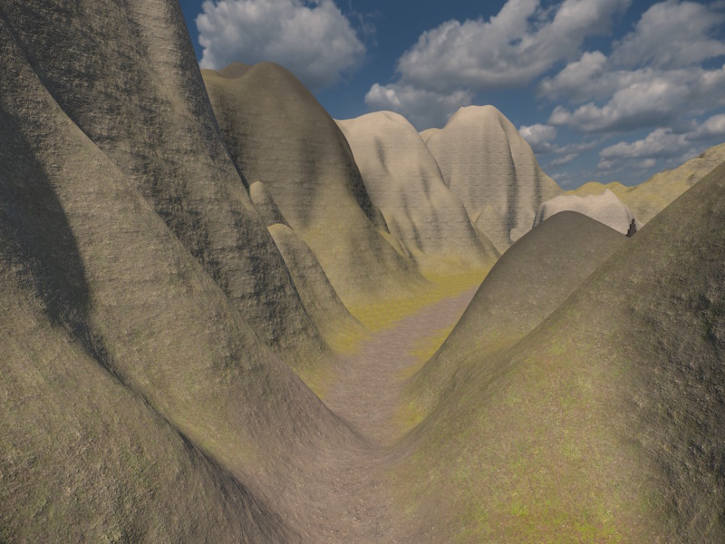
For an overview of the terrain system, see Terrain System.
Placement
You can place multiple terrain patches next to each other to cover large areas. Position each patch using its Size as the grid spacing, e.g. place patches with Size 64 exactly 64 units apart.
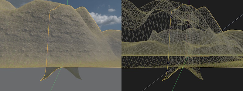
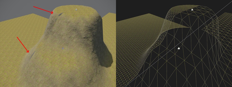
By default (unless LodCellPixelSize is set to 0), each patch renders a skirt: a downward strip of geometry around its border that overlaps into the neighboring patch. This hides the cracks that would otherwise appear where two patches meet, for instance if they render at different LOD levels, or use a different Resolution.
The image below shows what the expected overlap looks like. Here two patches are placed next to each other. Above ground they match perfectly, below ground you see the skirt geometry curving downwards.
The image below shows what those cracks would look like without a skirt (LodCellPixelSize set to 0 on both patches) and a mismatched vertex density (ie Size / Resolution):
Editing
Terrain patches are mostly edited through 2D terrain brushes. These are used to raise or lower the terrain and paint material layers on top. You can cut holes into terrain patches with 3D terrain brushes by setting them to Carve and enabling Affect Patches. This is mainly useful to cut entrances for caves. You will then need to model the entrance in some other way, either by placing some mesh or using the terrain volumes. Note, that modeling the transition from terrain into a cave is quite tricky to get right.
Performance
A good density for terrain patch vertices and quads is half a meter between vertices. So if your patch has a Size of 128 meters, use a Resolution of 256.
The renderer only culls entire patches, so prefer to use multiple smaller patches, than few huge ones. Also only place patches where you need them. If your level is long and thin, don't use patches that are much wider, rather place multiple thin ones in a row.
Terrain patches are much more memory efficient than terrain volumes. Use patches to cover large areas, use volumes only in places where you need overhangs. However, the pixel shader for patches can be more demanding, since terrain patches are able to blend many more material layers. If you determine that the material is too expensive, you can use a custom terrain material that blends fewer layers or does less complex operations.
Level of Detail (LOD)
Terrain patches automatically reduce their triangle count when the vertex density on screen exceeds what's needed, fading between LOD levels as the patch moves closer to or farther from the camera. LOD0 is the full resolution, LOD1 halves the vertex density in each direction (1/4 the triangle count), and LOD2 halves it again (1/16 the triangle count).
The detail level is controlled by the LodCellPixelSize property: once a single grid cell of the patch covers fewer pixels on screen than this value, the patch switches to the next coarser LOD. The on-screen size is measured at the point of the patch that is closest to the camera, and always relative to a view that is 1080 pixels high, so the chosen LOD doesn't depend on the window size or display resolution. The CVar Terrain.LodQuality is a global multiplier for LodCellPixelSize of all patches and can be used to implement a quality setting.
By default, skirt polygons are rendered around the border of each patch. This is a downward strip of geometry that overlaps with the neighboring patches, and is used to hide the cracks that would otherwise appear at the seam between patches, when neighboring patches render at different LOD levels or use different resolutions to begin with. The skirt is disabled when LodCellPixelSize is set to 0.
Occlusion Culling
Terrain patches can act as occluders for occlusion culling, so that objects behind hills and mountains are not rendered. For this, a coarse, decimated mesh of the terrain surface is generated. The level of detail of this mesh is controlled with the OcclusionCellSize property.
The occluder mesh is built from the same data as the collider, so a patch whose Collider is set to None gets no occluder either. The mesh is generated during scene export and when the editor starts the simulation. Therefore, patches don't occlude anything in the regular editor viewport, and changing OcclusionCellSize only takes effect the next time the mesh is generated.
To inspect the occluder geometry, enable the CVar Terrain.VisOccluder while the simulation is running.
Component Properties
Size — World-space side length of the patch. Combined with Resolution, this determines the distance between vertices.
Resolution — Number of quads per side. Higher resolutions produce finer detail but increase memory consumption.
Material — The material used to render the patch. Must use a heightfield-compatible shader. See Terrain Materials.
HeightImage — Optional grayscale ImageData asset used as a baseline height source. Brushes are applied on top of this image, not instead of it. When no image is assigned the baseline height is zero.
HeightImageOffset,HeightImageSize— UV offset and extent to select which part of the image will be used.HeightImageScale— Multiplier used to scale the height image values.BaseMaterialIndex— The material layer (0–31) assigned to vertices not covered by any brush.
LodCellPixelSize — The on-screen size in pixels (relative to a 1080 pixel high view) below which a grid cell makes the patch switch to the next coarser LOD level. Defaults to 16. Set to 0 ("LOD Disabled") to always render the patch at full resolution; this also turns off the skirt, since it is only needed to hide seams against a coarser LOD neighbor.
Collider — Controls whether and at what detail a physics collision shape is generated at scene export time. Lower values save memory, but lose detail. Colliders are needed when using procedural object placement. When possible, deactivate colliders (for far away terrain that's only there for decoration) or reduce its detail.
OcclusionCellSize — Size in meters of one cell of the occluder mesh. Larger values produce a coarser mesh, which is cheaper to rasterize but occludes less. The value can't be smaller than the grid spacing of the collider. Set to 0 ("Occlusion Disabled") to not generate an occluder for this patch.
Surfaces — Per-material-index physics surface array. Entry i is the surface used where material index i is dominant. Used to control physics behavior such as footstep sounds and friction per material layer.
TerrainTags — Identity tags assigned to this patch. A brush only affects this patch when the brush's own tags are either empty or contain at least one tag that matches. This can be used to apply brushes to only very specific objects and is only needed when you use multiple patches or terrain volumes on top of each other to form complex geometry. For instance you can rotate a terrain patch such that it points downward, to form the ceiling of a cave. In this case you may want to apply some brushes only to the floor and others only to the ceiling.